So.... Oops?
Video shows advance, but it retards, just had the wires backwards. NBD. Verified retardation after video was shot.
Password to view video is "rad". Should be done processing by approximately 6:30 GMT.
https://vimeo.com/56262425
https://vimeo.com/56262425
Monday, December 24, 2012
Friday, December 21, 2012
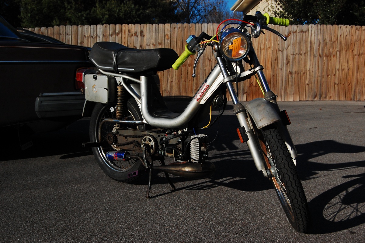
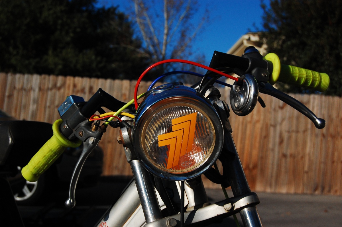
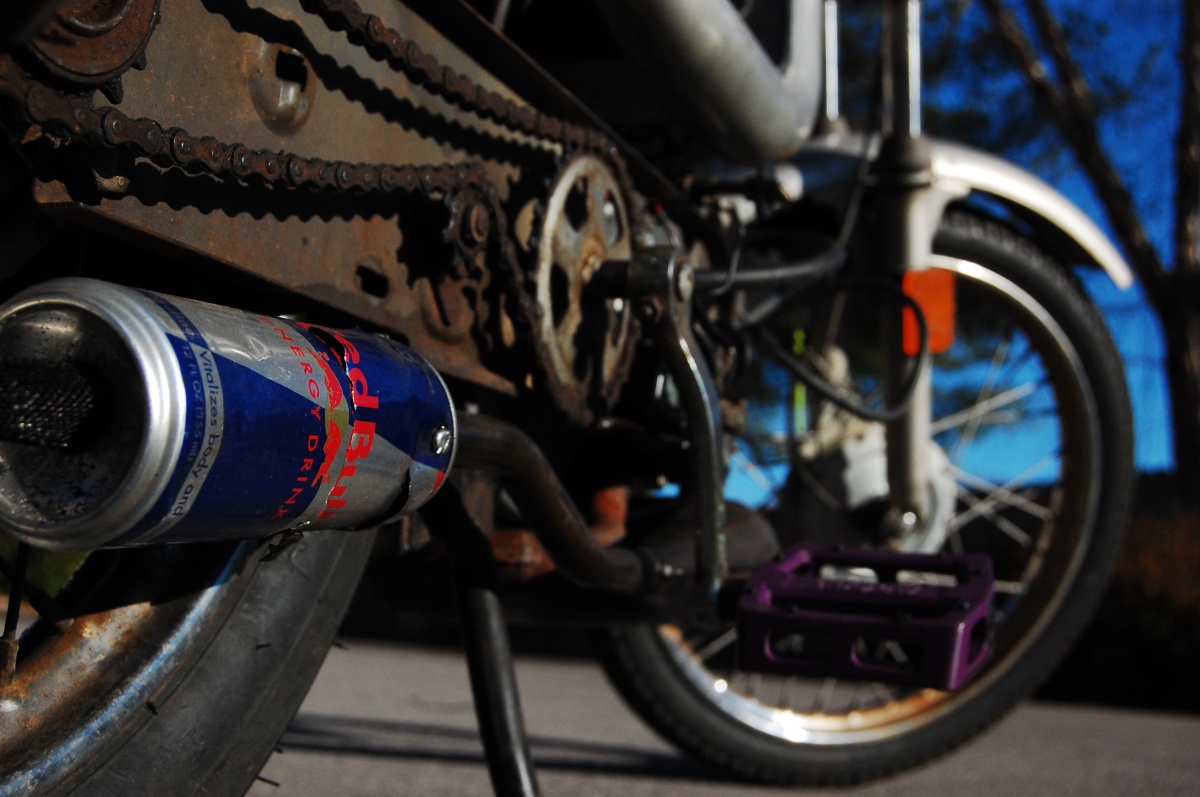
Sachs Ghetto Blaster
Yah... The tires are on backwards... you'll get over it.

Back to the garage to make ignition history!
Wednesday, December 19, 2012
Vespa Wiring in a Nutshell
Had a guy ask me about vespa wiring, and I sent this as a response. Figured I'd post it so more people than just him can enjoy it. This is written for bikes with turn signals, but applies to pretty much all vespas.
You should have four wires coming from your stator area if you have turn signals. Two should be white, one should be blue, and the other wire goes with the blue wire (don't remember color, could be any). Just the blue and violet if you don't have turn signals.
Power for lights and horn comes from the red plug in on the side of the case and the copper grounding strap. Red and black wires from your harness should plug in here respectively. This is 6VAC for lights and horn - but does NOT power your brake light, only your tail running light, headlight and horn.
The two white wires are a 6v coil with floated ground used to power a full wave rectifier and charge your lead acid battery which powers the turn signals - disregard these two if you don't care about turn signals.
The last two are the ones for the ignition. The blue/violet is for the HT coil. It has a split where it plugs into the wiring harness. One side goes directly to the HT coil, the other into the harness where the lead is grounded to the frame when you hit the kill switch dumping the ignition coil voltage to frame ground.
The ground lead from the ignition/exciter coil goes through the brake light switches and brake light filament. When the levers aren't pulled, the path of least resistance is through the switches and this is where if flows. When you pull the brake lever, it breaks the circuit through the switches that are dumping all the voltage from the other half wave of the ignition coil when they aren't pulled. This voltage needs to go somewhere so it goes through the filament of the bulb and lights your brake light.
Consequently, if your brake light is out and you pull the brakes, there'll be nothing for the ignition to ground to, you'll lose spark and your bike will shut off. It's a safety feature from Vespa.
Here's a harness for a Grande with turnsignals I use to troubleshoot my bike. Click on the image, right click and select "view image". Then you can zoom in to read detail.

Next step is to verify your kill switch is working. Turn the bike to "OFF" - you should have continuity (close to zero resistance). Now turn the bike back "ON". You should be showing some resistance or an open circuit. If you have zero resistance when the bike is in the "RUN" position, you've got a short somewhere. You must find this short before the HT coil will spark the plug.
*Note: Make sure you know the difference between open circuit and zero resistance. To see open circuit, disconnect the leads from everything - this display reading is open circuit. Now touch the two leads together while reading resistance - it should go to 0.00. This is zero resistance continuity.
Cool! Your kill switch works!
If you HAVE voltage, SKIP to STEP 6.
Once you have found this wire, set your meter to ohms. Connect to the wire on the wiring harness/the bike that is blue or was connected to blue AND frame ground. You should read zero resistance continuous. Pull the brake lever - you should see a slight increase in resistance. If you do not and your meter reads an open circuit, your brake light bulb is missing or the filament is out.
If everything here checks out, continue. If it doesn't, fix it, then repeat step 2.
COOL! Everything outside your engine is working as it should... time to investigate under the flywheel.
 At this position, the points should be open. If they are not, adjust them until they are. You must loosen the screw and push the points against the points cam to increase the gap - this can be done with a screwdriver. Demonstration here @ 2:15 on how to set the points. You'll need a feeler gauge (or a good guess) and set them to .3-.5mm range and this should get it to run. You'll want to set timing to 17-19* BTDC once you get it running (worry about that later).
Now, lets clean the points. Take a fine grit paper (400-1000 will do) and rub it between the points - you are trying to remove oxidation and crud from the contact surfaces of the points so they can electrically connect. It is much easier to do this with the flywheel off, but you need a flywheel puller.
After the points are cleaned, gapped and still closing, repeat STEP 2. If STEP 2 fails, continue on.
For this step, you will need to remove the flywheel unless you have an externally mounted condenser. You will not have an externally mounted condenser unless your bike had turn signals. Even so, you'll probably still have to remove the engine.
You will need this special tool to remove the flywheel.
 Once you have the engine out and the flywheel removed, you want to test the resistance across the exciter coil. You want this to measure anywhere between .1 and 2 ohms. Open circuit is bad. If you have an open circuit, you did the test wrong, or you need a new coil. So make sure you did it right before ordering a new coil.
In order to get a useful reading, remove the points, condenser and exciter coil from the case and connect the voltmeter to the blue wire/wire that was connected to the blue wire on the wiring harness AND the other lead is connected to somewhere inbetween the coil and the condenser (this should be the violet side of the coil). A good place to connect your second lead is to the solder connection on the coil or to the solder connection on the condenser. Make sure the wire ends are not touching anything.
If your bike passes this test and still doesn't pass test 2, you likely need a new condenser. Replace the condenser and repeat STEP 2.
It's time to check the HT coil. Measure the resistance between the spade terminal and frame ground - it should be in the 1-4 ohms. If it is open circuit, you need a new HT coil. If it is excessively high or less than 1, you likely need a new HT coil or have a bad HT coil ground.
Next remove the spark plug wire from the HT coil, or remove the spark plug boot from the end of the spark plug wire and insert the voltmeter lead into the spark plug wire innards to make contact with the conducting filament or screw inside the HT coil the plug wire screws onto. Measure resistance between frame ground and the screw connection/inside of the spark plug wire. This should read in the 10's. If it is open circuit, you need a new HT coil or have a bad HT coil ground. If it passes one HT coil test, but not the other, it is likely the coil and not the ground that is bad.
To test the spark boot, put one test lead on on the coarse threads that thread into the spark plug wire, and one end on the other end ensure you are making contact with the contact that touches the electrode tip of the plug. You should read 5k ohms for the stock boot (it also should be marked) if you read open circuit you need a new plug boot. If you have a different than stock plug boot you may have more, less or no resistance - it should never be open circuit though.
If your meter isn't autoranging, make sure you aren't trying to test outside the range of your current setting.
If your bike has weak spark and all your zero resistance continuous checks are good, try increasing your point gap slightly. If you increase the point gap so much that the points never close, your bike will not spark. Once you have your bike running, try to find the factory ignition timing and gap specs and set the bike to those.
An Overview
You should have four wires coming from your stator area if you have turn signals. Two should be white, one should be blue, and the other wire goes with the blue wire (don't remember color, could be any). Just the blue and violet if you don't have turn signals.
Power for lights and horn comes from the red plug in on the side of the case and the copper grounding strap. Red and black wires from your harness should plug in here respectively. This is 6VAC for lights and horn - but does NOT power your brake light, only your tail running light, headlight and horn.
The two white wires are a 6v coil with floated ground used to power a full wave rectifier and charge your lead acid battery which powers the turn signals - disregard these two if you don't care about turn signals.
The last two are the ones for the ignition. The blue/violet is for the HT coil. It has a split where it plugs into the wiring harness. One side goes directly to the HT coil, the other into the harness where the lead is grounded to the frame when you hit the kill switch dumping the ignition coil voltage to frame ground.
The ground lead from the ignition/exciter coil goes through the brake light switches and brake light filament. When the levers aren't pulled, the path of least resistance is through the switches and this is where if flows. When you pull the brake lever, it breaks the circuit through the switches that are dumping all the voltage from the other half wave of the ignition coil when they aren't pulled. This voltage needs to go somewhere so it goes through the filament of the bulb and lights your brake light.
Consequently, if your brake light is out and you pull the brakes, there'll be nothing for the ignition to ground to, you'll lose spark and your bike will shut off. It's a safety feature from Vespa.
Here's a harness for a Grande with turnsignals I use to troubleshoot my bike. Click on the image, right click and select "view image". Then you can zoom in to read detail.

Have you lost your spark? Let me help you find it.
STEP 1
First things first. Find your HT coil - this is the box that your spark plug wire is connected to. You should have ONE wire coming into it connected to a spade terminal. Remove that wire (it is likely violet) and connect your voltmeter to that wire and frame ground. |
| this is what an HT (high tension) coil looks like. Notice the spade connector in the center of the picture. |
Next step is to verify your kill switch is working. Turn the bike to "OFF" - you should have continuity (close to zero resistance). Now turn the bike back "ON". You should be showing some resistance or an open circuit. If you have zero resistance when the bike is in the "RUN" position, you've got a short somewhere. You must find this short before the HT coil will spark the plug.
*Note: Make sure you know the difference between open circuit and zero resistance. To see open circuit, disconnect the leads from everything - this display reading is open circuit. Now touch the two leads together while reading resistance - it should go to 0.00. This is zero resistance continuity.
Cool! Your kill switch works!
STEP 2
Now, let's check for voltage at the HT coil. Leave the voltmeter connected to the wire going in the HT coil and switch your voltmeter to read voltage. Try to start the bike by turning the engine over. If you don't see at least 3-6volts - it's likely that you won't see spark. If you see less than 1v, you have a weak coil or draw somewhere between your coil and your spade connector going into your HT coil. If you have voltage here, it's likely that you have a bad HT coil. If you have no voltage, please continue.If you HAVE voltage, SKIP to STEP 6.
STEP 3
Next step is to verify that your exciter coil is grounding so it can send a pulse to the HT coil. Find the BLUE wire coming from your engine, disconnect the blue wire (and leave the violet wire disconnected as well). DO NOT connect your volt meter to the blue wire going in to the engine, but instead, connect it to the plug on the wiring harness where your blue wire unplugged from. If you do not have a blue wire, the wire you need to connect to is the one that is not violet, is not connected to violet and is not grey.Once you have found this wire, set your meter to ohms. Connect to the wire on the wiring harness/the bike that is blue or was connected to blue AND frame ground. You should read zero resistance continuous. Pull the brake lever - you should see a slight increase in resistance. If you do not and your meter reads an open circuit, your brake light bulb is missing or the filament is out.
If everything here checks out, continue. If it doesn't, fix it, then repeat step 2.
COOL! Everything outside your engine is working as it should... time to investigate under the flywheel.
STEP 4
Time to clean and gap those points! Remove the rubber plug from your flywheel. Rotate it until you can see the points. They look like this:
Now, lets clean the points. Take a fine grit paper (400-1000 will do) and rub it between the points - you are trying to remove oxidation and crud from the contact surfaces of the points so they can electrically connect. It is much easier to do this with the flywheel off, but you need a flywheel puller.
After the points are cleaned, gapped and still closing, repeat STEP 2. If STEP 2 fails, continue on.
STEP 5
At this point, one of two things has happened. You suck and can't get your bike to pass test two because you suck at cleaning points OR your coil or condenser are bad. The later is more common than the former. So if you don't want to pull your engine out, try to do a better job of cleaning those points and getting your bike to pass test 2!For this step, you will need to remove the flywheel unless you have an externally mounted condenser. You will not have an externally mounted condenser unless your bike had turn signals. Even so, you'll probably still have to remove the engine.
You will need this special tool to remove the flywheel.

In order to get a useful reading, remove the points, condenser and exciter coil from the case and connect the voltmeter to the blue wire/wire that was connected to the blue wire on the wiring harness AND the other lead is connected to somewhere inbetween the coil and the condenser (this should be the violet side of the coil). A good place to connect your second lead is to the solder connection on the coil or to the solder connection on the condenser. Make sure the wire ends are not touching anything.
If your bike passes this test and still doesn't pass test 2, you likely need a new condenser. Replace the condenser and repeat STEP 2.
STEP 6
So, you HAVE VOLTAGE from your violet wire. YAY! If you don't, turn yourself around and go back to step two.It's time to check the HT coil. Measure the resistance between the spade terminal and frame ground - it should be in the 1-4 ohms. If it is open circuit, you need a new HT coil. If it is excessively high or less than 1, you likely need a new HT coil or have a bad HT coil ground.
Next remove the spark plug wire from the HT coil, or remove the spark plug boot from the end of the spark plug wire and insert the voltmeter lead into the spark plug wire innards to make contact with the conducting filament or screw inside the HT coil the plug wire screws onto. Measure resistance between frame ground and the screw connection/inside of the spark plug wire. This should read in the 10's. If it is open circuit, you need a new HT coil or have a bad HT coil ground. If it passes one HT coil test, but not the other, it is likely the coil and not the ground that is bad.
STEP 7
Test your plug wire and spark plug boot next. Your plug wire from end to end WITHOUT the spark plug boot should be zero continuous unless it's a resistor wire (should be marked if it is).To test the spark boot, put one test lead on on the coarse threads that thread into the spark plug wire, and one end on the other end ensure you are making contact with the contact that touches the electrode tip of the plug. You should read 5k ohms for the stock boot (it also should be marked) if you read open circuit you need a new plug boot. If you have a different than stock plug boot you may have more, less or no resistance - it should never be open circuit though.
If your meter isn't autoranging, make sure you aren't trying to test outside the range of your current setting.
STEP 8
If your bike has passed all these tests - you have done the tests incorrectly.If your bike has weak spark and all your zero resistance continuous checks are good, try increasing your point gap slightly. If you increase the point gap so much that the points never close, your bike will not spark. Once you have your bike running, try to find the factory ignition timing and gap specs and set the bike to those.
STEP 9
Ride your damn moped.Tuesday, December 18, 2012
Kreidler Clutch Puller
Here's a drawing of a kreidler puller I made - the ring is just a thick or several thick washers. Uploaded for Doug on MA. Enjoy.


Thursday, December 13, 2012
HPI boxes restocked at treats!
Just ordered one and had it sent home! Can't wait to get done with my last two exams today! Wish me luck! I need an 82 on one of my finals to avoid repeating the course! (minimum C required for credit).

Wednesday, December 12, 2012
HPI Experimentation: Rheostat
Instead of multiple resistors and dialing in wire gauges - I'm going to use a rheostat. BAM. Didn't think a that did ya. Now to look at power ratings for rheostats... hmmmmmm

Monday, December 10, 2012
HPI Experimentation: First Blood
So a lot has happened since the last time I posted too! Unfortunately, I still don't have an ignition with a significant fun curve for less than $300 that has lights, but here's my progress.
There is no trigger coil for HPI. HPI is a TCI ignition. It fires based off of peak exciter coil voltage not from a trigger. Don't believe me? Check out the resistance/continuity readings from the stator.
Blue and white are both ends of the exciter coil and black is just frame ground for the box. If the stator had trigger AND exciter coils, then there would be continuity to ground for blue and white. With one having a 300-400 ohm reading (exciter) and one with 30-70ish reading (trigger).
From there, I generated a spreadsheet to calculate/play with coil dimensions and gauge to estimate wire gauge on existing coils. It assumes ideal winding, but like I said, it's just for estimation to get you in a ballpark. You can download that spreadsheet here.
Important Note: When you use the spread sheet, whenever you change the coil dimensions or the wire gauge, you have to manually enter the nearest whole number from "ideal turns" into "actual turns" and maybe put it a bit lower since you aren't going to perfectly wrap the coil.

Keep in mind we're trying to match existing resistances and dimensions to find a length and gauge of wire suitable. Resistance has no effect on voltage, it's only for guesstimating a size. If you choose too small of a gauge it may not be able to supply ample current, but I haven't encountered that yet.
I emailed HPI and got the ballpark voltages off of the stator we are shooting for, Here's how their email reads:
So your goal should be 50VDC at no more than 380VDC.
I used a drill and spool setup. I went with 38gauge and wound near all of the 1200ft I had. First time I wrapped it, the wire fatigued at the point of entry to the coil. To get around that, I used the smallest heat shrink I have to go over the winding wire about 1cm onto the coil and stick out a good bit from the coil.


Then like the awesome person I am, I worked with the connector manufacturer to find the connectors for the HPI box in the states and through lots and lots of phone calls and emails, I have a source for these connectors. I'll start selling them if I get this mod dialed in.
 Like a n00b, when I got the bike started I hopped on it and rode it around. It cut out after about 5 minutes.
When I went through checking for what it could be, I pushed it with the
stator spinning and just at a PUSHING speed - voltage was well into the mid
300VAC. So right now I'm assuming my box is fried, but I'm going to wait to call that until I hook it up to an HPI stator on a bike.
Like a n00b, when I got the bike started I hopped on it and rode it around. It cut out after about 5 minutes.
When I went through checking for what it could be, I pushed it with the
stator spinning and just at a PUSHING speed - voltage was well into the mid
300VAC. So right now I'm assuming my box is fried, but I'm going to wait to call that until I hook it up to an HPI stator on a bike.
This is super depressing it broke, but also exciting because it seems 300VAC isn't so hard to generate.
Crazy Wayne from MA stepped in and informed me that with a rotor over coil ignition, my magnets were going to be moving at a higher velocity - which is obvious now but I totally hadn't thought of it. This make sense because I was using a comparable length of wire to what I had calculated was in the HPI coil on the inner rotor. So instead of being less efficient, the rotor OVER coil systems are actually more "efficient" powerful, whatever - it doesn't take as much to generate voltage on them.
So it does run, whether or not well or with a curve or not, I don't know...
The next magic step will be dialing in gauge for resistance after I get the voltage right.
I'm currently waiting on boxes to be restocked at treats or 1977 mopeds and for final exams to be over with... I have a diffeq exam tomorrow and a very crucial ME exam that I need to do well on.
Wish me luck! Tons to come starting the 15th when I get back to my garage and all my bikes!
the 80cc sachs 3 speed
the UPS polini HPI homoet 6p magnum
the vespa gets an HPI cdi box?
transmission cooling on a ZA50
I can't wait to post about all those! I've got the parts stowed and the enthusiasm mustered!
There is no trigger coil for HPI. HPI is a TCI ignition. It fires based off of peak exciter coil voltage not from a trigger. Don't believe me? Check out the resistance/continuity readings from the stator.
Blue and white are both ends of the exciter coil and black is just frame ground for the box. If the stator had trigger AND exciter coils, then there would be continuity to ground for blue and white. With one having a 300-400 ohm reading (exciter) and one with 30-70ish reading (trigger).
 | |
| Black and blue continuity test - overload (no continuity) |
 |
| Black and white continuity test - overload (no continuity) |
 |
| White and blue continuity test - continuity 367ohms resistance over the coil no continuity with ground |
 |
From left to right: pin1 Blue (one end of exciter coil), pin2 White (other end of exciter coil), pin3 Black (frame ground) |
From there, I generated a spreadsheet to calculate/play with coil dimensions and gauge to estimate wire gauge on existing coils. It assumes ideal winding, but like I said, it's just for estimation to get you in a ballpark. You can download that spreadsheet here.
Important Note: When you use the spread sheet, whenever you change the coil dimensions or the wire gauge, you have to manually enter the nearest whole number from "ideal turns" into "actual turns" and maybe put it a bit lower since you aren't going to perfectly wrap the coil.
Keep in mind we're trying to match existing resistances and dimensions to find a length and gauge of wire suitable. Resistance has no effect on voltage, it's only for guesstimating a size. If you choose too small of a gauge it may not be able to supply ample current, but I haven't encountered that yet.
I emailed HPI and got the ballpark voltages off of the stator we are shooting for, Here's how their email reads:
hello Ryan
the resistans off 370 looks Ok
the voltage AC is going from 50 til 380 V on bleu and white til 12000 rpm
please look with a strobe to see the advance and after the retard from about 20° til 12000
regards
willy
So your goal should be 50VDC at no more than 380VDC.
I used a drill and spool setup. I went with 38gauge and wound near all of the 1200ft I had. First time I wrapped it, the wire fatigued at the point of entry to the coil. To get around that, I used the smallest heat shrink I have to go over the winding wire about 1cm onto the coil and stick out a good bit from the coil.
Then like the awesome person I am, I worked with the connector manufacturer to find the connectors for the HPI box in the states and through lots and lots of phone calls and emails, I have a source for these connectors. I'll start selling them if I get this mod dialed in.
This is super depressing it broke, but also exciting because it seems 300VAC isn't so hard to generate.
Crazy Wayne from MA stepped in and informed me that with a rotor over coil ignition, my magnets were going to be moving at a higher velocity - which is obvious now but I totally hadn't thought of it. This make sense because I was using a comparable length of wire to what I had calculated was in the HPI coil on the inner rotor. So instead of being less efficient, the rotor OVER coil systems are actually more "efficient" powerful, whatever - it doesn't take as much to generate voltage on them.
So it does run, whether or not well or with a curve or not, I don't know...
The next magic step will be dialing in gauge for resistance after I get the voltage right.
I'm currently waiting on boxes to be restocked at treats or 1977 mopeds and for final exams to be over with... I have a diffeq exam tomorrow and a very crucial ME exam that I need to do well on.
Wish me luck! Tons to come starting the 15th when I get back to my garage and all my bikes!
the 80cc sachs 3 speed
the UPS polini HPI homoet 6p magnum
the vespa gets an HPI cdi box?
transmission cooling on a ZA50
I can't wait to post about all those! I've got the parts stowed and the enthusiasm mustered!
Thursday, November 15, 2012
Vespa Shenanigans
So quite a bit has happened to the vespa since I posted last. I gave up lightening the brass weights.
It now has a Kinetic CDI... It's static which I hate. I absolutely hate hate hate that all of my bikes have static ignitions - it's just so dumb. Going to try and experiment with the HPI cdi box since it's fired by peak voltage instead of a trigger coil.
In addition to the CDI, I've also made some lighter weight aluminum roller weights for the variator. A lot of people destroy or flat spot their roller casings with "home made" weights, but I feel like this is because they use nuts etc. for weights - I purchased 11mm diameter aluminum bar stock to make mine, so there is no unsupported surface on the rollers. They're 2.8 grams and fantastic. I think this is going to be the next thing to add to the "davy sprocket" parts line on treats.

Right now the vespa is hitting 380*F ish... I attribute this to low gearing and static timing. Race gears are $85 and a variator is $110. I figured I'd go with modified stock on the variator and try to adapt an HPI box over christmas. I recently picked up a 12.10 carb from Brad to drill out to 13mm as well as a spare set of ramp plates to have a go at a notching attempt on. I'd say it went pretty well.
Also, I go some new cable housing, some new bars, some new grips and some new tires! Huzzah! Finishing up the wiring and cables in my apartment before I sneak it back down past the RA's to be locked up outside :(

It now has a Kinetic CDI... It's static which I hate. I absolutely hate hate hate that all of my bikes have static ignitions - it's just so dumb. Going to try and experiment with the HPI cdi box since it's fired by peak voltage instead of a trigger coil.
In addition to the CDI, I've also made some lighter weight aluminum roller weights for the variator. A lot of people destroy or flat spot their roller casings with "home made" weights, but I feel like this is because they use nuts etc. for weights - I purchased 11mm diameter aluminum bar stock to make mine, so there is no unsupported surface on the rollers. They're 2.8 grams and fantastic. I think this is going to be the next thing to add to the "davy sprocket" parts line on treats.
Right now the vespa is hitting 380*F ish... I attribute this to low gearing and static timing. Race gears are $85 and a variator is $110. I figured I'd go with modified stock on the variator and try to adapt an HPI box over christmas. I recently picked up a 12.10 carb from Brad to drill out to 13mm as well as a spare set of ramp plates to have a go at a notching attempt on. I'd say it went pretty well.
 |
| I stuck with 12mm notch height - the optimum range is 12-10mm I hear. |
 |
| I tried to sorta match what the ramp would turn into at this point in the wall - we'll see if it does any good. |
 |
| Obviously, how the roller is going to travel up the new notched wall. |
 | ||
| This is how far out the roller should travel. Whether or not it's going to get stuck on the outer ramp plate is yet to be seen, but I'd say it's definitely a possibility. |
Monday, October 1, 2012
So, the vespa is finally running great... Kinetic CDI is here, and variator is getting dialed in.
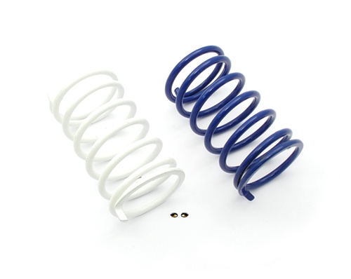
Right now I'm at 6% weight reduction with the stock brass weights, next step will be around 10-11% reduction with the lighter polini spring. 6% puts full variation at about 20mph.
Currently tops out at 45mph with an un-notched variator and a 12mm carb... as soon as I get the variation good, I'll notch the vario.
I got a job working at River Sports Outdoors as a bicycle mechanic, so hope to get some new funds rolling in... wanna build some bike wheels and some sick mopeds for rally season.

The PucHonda video is finally finished... I've sent it in to iron and air to try and get them to take ahold of it on their facebook page... we'll see if they think it's cool enough.
Puchonda from Ryan on Vimeo.
Right now I'm at 6% weight reduction with the stock brass weights, next step will be around 10-11% reduction with the lighter polini spring. 6% puts full variation at about 20mph.
Currently tops out at 45mph with an un-notched variator and a 12mm carb... as soon as I get the variation good, I'll notch the vario.
I got a job working at River Sports Outdoors as a bicycle mechanic, so hope to get some new funds rolling in... wanna build some bike wheels and some sick mopeds for rally season.
The PucHonda video is finally finished... I've sent it in to iron and air to try and get them to take ahold of it on their facebook page... we'll see if they think it's cool enough.
Puchonda from Ryan on Vimeo.
Tuesday, September 18, 2012
Tuesday, September 11, 2012

Friday, September 7, 2012
mechanical moped Ignition Advance
Ok, so, the other day, I threw around the idea of a vacuum advanced full loss battery powered ignition for mopeds on the forums. It's simple. Get a pneumatic cylinder, some linkages and a return spring, tap your intake for a nipple and go...
these are the cylinders I had in mind:
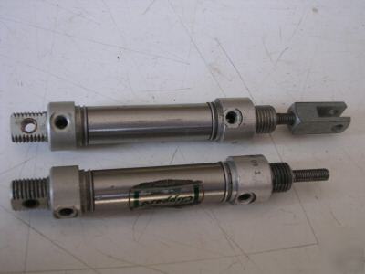
That's cool because it's automatic and all, but you'd have to fool with spring tensions, regulating the vacuum so it didn't advance too soon, worrying about it jamming and blowing your motor etc. etc. etc.
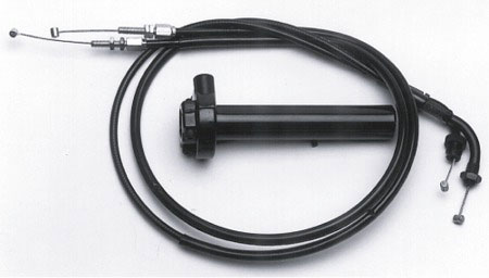
I was watching some videos today and apparently, old indians have left and right twist grips. One for the distributor and one for the throttle...
Cable linkages would be so much more fun, reliable and just BA.
 Seems simple enough. I think I'll do this to the 80cc reedvalve sachs motor, because the my mk65 za50 maxi won't rev that high and neither will my 70cc tccd za50'd swinger 1...
Maybe I'll run it on the rat polini magnum for the nashville rally next year... ugh, that's what I was planning on using the HPI internal rotor for though. I have stock piled so many parts and need to build so many motors.
these are the cylinders I had in mind:
That's cool because it's automatic and all, but you'd have to fool with spring tensions, regulating the vacuum so it didn't advance too soon, worrying about it jamming and blowing your motor etc. etc. etc.
I was watching some videos today and apparently, old indians have left and right twist grips. One for the distributor and one for the throttle...
Cable linkages would be so much more fun, reliable and just BA.
Maybe I'll run it on the rat polini magnum for the nashville rally next year... ugh, that's what I was planning on using the HPI internal rotor for though. I have stock piled so many parts and need to build so many motors.
Tuesday, September 4, 2012
OH HEHROW!
It's the beginning of September... I am currently:
saving up for Vespa performance stuff

trying to find transmission parts for a 505/3BX for willd

finish the motorcycle build video
draw angled sachs intake risers in auto desk
build engines for next year....
Something is bound to happen with one of these soon... I'm waiting on funds for the vespa, peeps in germany for will, a riding shot for the video and idk what for on the last one.
Yup... OH, and school, but that's not interesting. BLARGH. DiffEq round 2
Subscribe to:
Posts (Atom)